
- #Wire h library download how to#
- #Wire h library download serial#
- #Wire h library download driver#
- #Wire h library download code#
#Wire h library download driver#
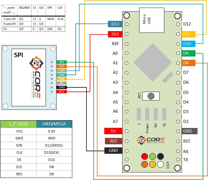
The 4 pins of the i2c LCD driver module are connected as per the circuit diagram. Using only two pins A4 and A5 we can control the 16×2 LCD. The VCC pin is connected with the Arduino’s 5 volts, the SDA pin is connected with the Arduino’s Analog pin A4, the SCL pin is connected with the Arduino’s Analog pin A5, while the GND pin is connected with the Arduino’s ground. Using these connections you can convert any 16×2 LCD into an i2c supported LCD. All the 16 pins of the PCF8574 driver module are connected with the LCD pins. The links control the least significant 3 bits, fitting the link sets the bit low.Īs you can see the circuit diagram is really simple. As you can see no links are fitted the 7-bit address is 0x27 which you have to confirm in the datasheet, may be your LCD have a different i2c address. I2c addresses:Īs you can see the driver module is also provided with A0, A1, and A2 links which can be used to set the i2c address. A 10K variable resistor which is used for the adjustment of the LCD contrast. The four male headers are clearly labeled as GND, VCC, SDA, and SCL. This is just a normal 16×2 LCD which is converted into an i2c supported type LCD by using the PCF8574 i2c Driver module.

I would appreciate your support in this way! I may make a commission if you buy the components through these links. The components and tools used in this project can be purchased from the and Amazon, the components Purchase links are given below: Without any further delay let’s get started!!! In this tutorial you will also learn how the same i2c 16×2 LCD can be interfaced with the Nodemcu ESP8266 Wifi Module which used in IOT based projects.
#Wire h library download how to#
In this tutorial, you will learn how to display text on the i2c 16×2 LCD using Arduino. This type of the LCD can be interfaced with any controller board using only 2 wires. The i2c 16×2 LCD is in fact the same LCD but it comes with the i2c driver module soldered on the backside of the LCD The wiring can be reduced by replacing a regular 16×2 LCD with the I2C supported 16×2 LCD. A regular 16×2 LCD module needs a lot of wires, due to which maximum of the controller I/O pins are wasted. For displaying the Date and time information, In a password-protected door security system, and so on.
#Wire h library download code#

Serial.println("About to initialize sensor") This example shows how to take simple range measurements with the VL53L1X. I have also modified slightly the “Continuous” example as below: /*

Changing the SDA and SCL the dedicated SDA and SCL ports on the board does not change anything.
#Wire h library download serial#
The Arduino Uno board also has dedicated SDA and SCL ports, again connecting the carrier (Vin to 5V, GND to GND, SDA to SDA and SCL to SCL ) we get the same results, measures appear without further problem.Īnd just for checks, I tried the very same things connecting to the 3.3V outlet of the Arduino Uno and it worked perfectly.Ĭonnecting the Carrier (Vin to 3.3V, GND to GND, SDA to A4 and SCL to A5) to a Arduino 101and uploading the example “Continuous” when I open the serial monitor, nothing appears. I am going to try to write down all the tests I have done to try to help you as much as I can.Ĭonnecting the Carrier (Vin to 5V, GND to GND, SDA to A4 and SCL to A5) to a Arduino Uno and uploading the example “Continuous” everything works fine, As soon as the sketch is uploaded I open the serial monitor and measures appear.


 0 kommentar(er)
